1. Servo Sweep
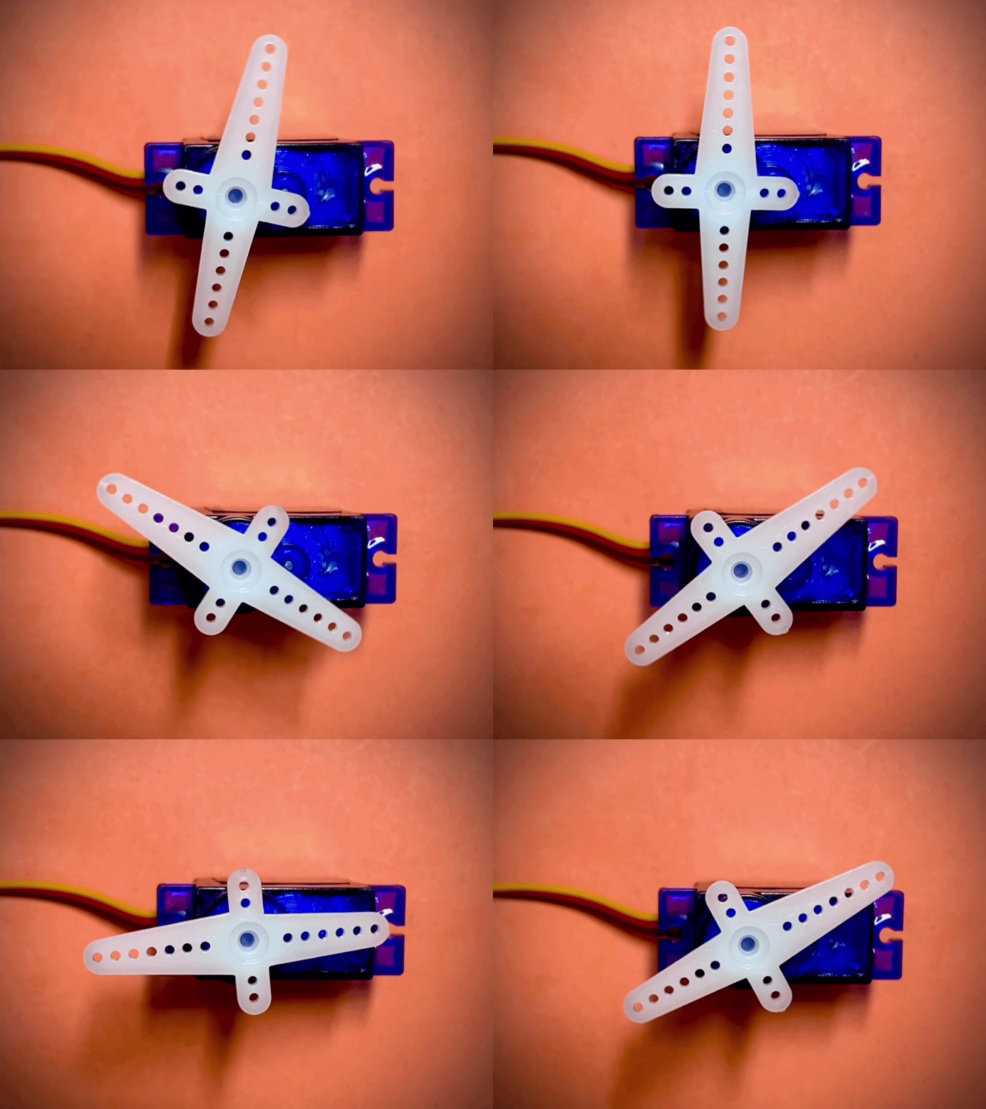
In this tutorial, we’ll write a complete hardware design in Verilog to control an SG90 servo motor using the Soan Papdi and the Apio CLI.
Connecting the Servo
First things first, let’s wire up the hardware. Connect your SG90 servo motor to the Soan Papdi as shown below:
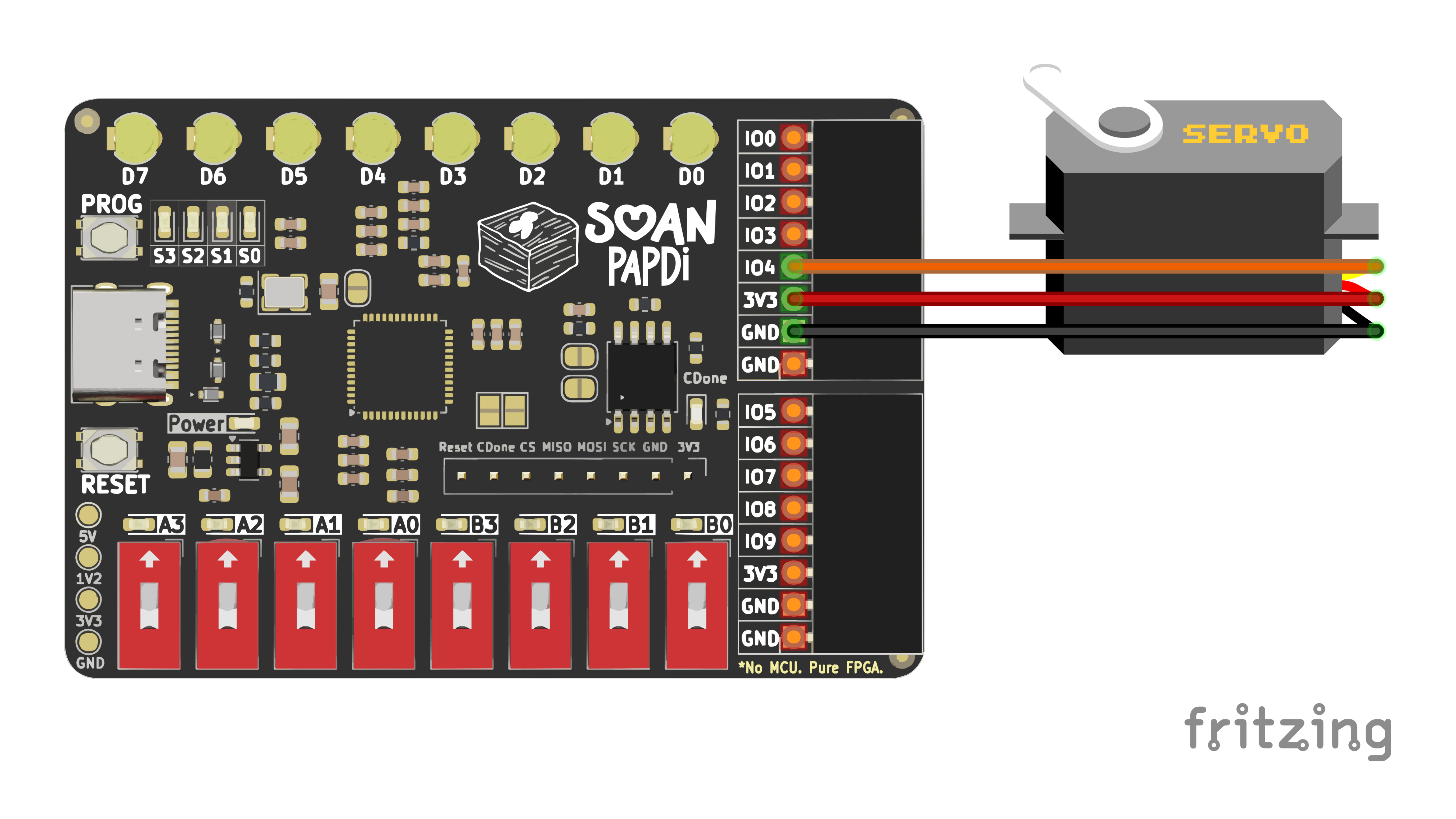
| SG90 Servo Wire | Soan Papdi Pin |
|---|---|
| Signal (Orange) | IO4 (Pin 23) |
| VCC (Red) | VCC |
| GND (Brown/Black) | GND |
Note: For this example, we are using IO4 (which maps to Pin 23), but you can configure your code to use almost any other GPIO pin.
Need to find a different pin? Check out the full Pin Diagram.
Clone the Example Project
Instead of typing everything from scratch, let’s grab the example code from Github. Open your terminal and run:
git clone https://github.com/hardik1975/soan-papdi-examples.gitMove into the project directory:
cd soan-papdi-examples/01-servo-sweepFile Structure
An Apio project requires three main files to work:
01-servo-sweep/
│
├── apio.ini       → Board & configuration settings
├── pins.pcf       → Physical pin mappings
└── servo.v        → Your Verilog code
Let’s look at what each one does!
1. apio.ini
This file tells Apio what hardware you are building for and where your code starts.
[env:default]
board = soan-papdi
top-module = servo_sweep
board = soan-papdi: Tells APIO you are using the Soan Papdi board.top-module = servo_sweep: The main starting point of your Verilog code. This must perfectly match the module name inside your.vfile.
2. pins.pcf
This file maps the signal names used in your Verilog code to the actual physical pin numbers on the Soan Papdi board.
# 12 MHz Clock
set_io clk 35

# Servo Signal Output
set_io servo 23
set_io clk 35: Assigns theclksignal in your code to physical Pin 35 (the on-board 12 MHz oscillator).set_io servo 23: Assigns theservosignal in your code to Pin 23 on the header (where you plugged in the orange signal wire).
3. servo.v
This is your main Verilog file. It generates a 50 Hz PWM (Pulse Width Modulation) signal to control the servo angle and sweeps it back and forth continuously.
Unlike software that runs line-by-line on a processor, Verilog code is used to physically wire up logic gates, timers, and comparators inside the FPGA. Let’s break down how servo.v works.
Understanding the Verilog Logic
Module Declaration
Every Verilog design starts with a module. Think of a module as a reusable hardware block with input and output pins.
module servo_sweep (
    input  wire clk,
    output reg  servo
);
input wire clk: The 12 MHz clock oscillator on the Soan Papdi drives this line, ticking 12,000,000 times per second.output reg servo: Declared as areg(register) because its state (0 or 1) is updated inside analwaysblock, meaning it needs to hold its value between clock cycles.
Time-to-Clock Math
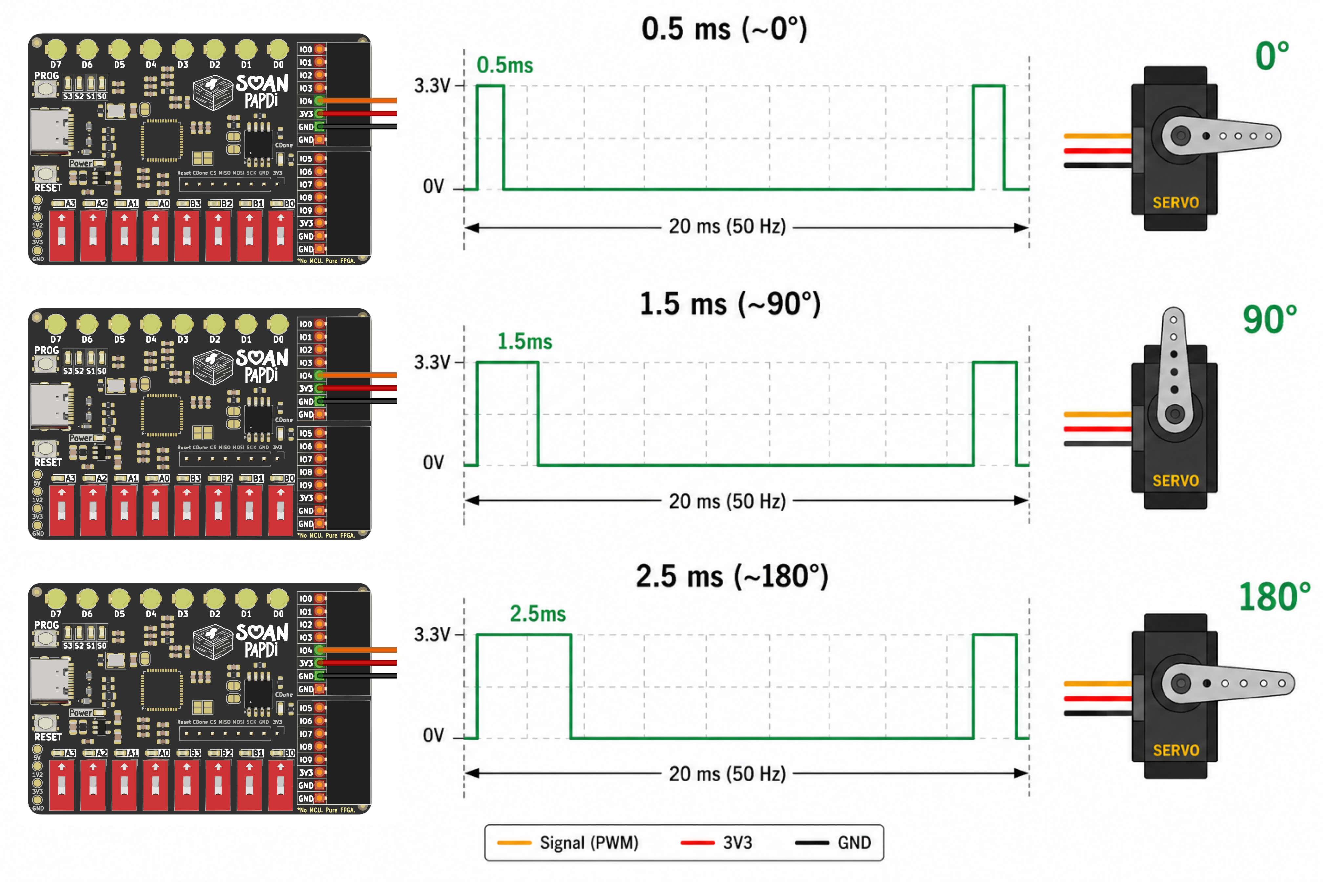
Servo motors are controlled by a 50 Hz PWM signal, which means a new pulse is sent every 20 milliseconds. The width of this high pulse dictates the angle of the servo shaft.
localparam PERIOD    = 240000; // 20ms full frame
localparam MIN_PULSE = 6000;   // 0.5ms (~0 degrees)
localparam MAX_PULSE = 30000;  // 2.5ms (~180 degrees)
Because our FPGA clock ticks at 12 MHz, we need to convert human time into clock cycles:
- Period Ticks: 12,000,000 Hz × 0.020 s = 240,000 cycles
- 0.5 ms Ticks: 12,000,000 Hz × 0.0005 s = 6,000 cycles
- 2.5 ms Ticks: 12,000,000 Hz × 0.0025 s = 30,000 cycles
Registers & Bit Sizing
Unlike variables in software (where an int is always 32 or 64 bits), registers become physical memory elements in hardware. You must specify exactly how many bits each counter needs to save space.
reg [17:0] pwm_counter   = 0;
reg [15:0] pulse_width   = MIN_PULSE;
reg        direction     = 1'b1;
reg [20:0] speed_counter = 0;
reg [17:0] pwm_counter: 18 bits gives us a max value of 262,143—just enough to safely count to 240,000.reg [15:0] pulse_width: 16 bits gives us a max value of 65,535—easily covering ourMAX_PULSEof 30,000.reg direction: A single bit (1'b1for sweeping up,1'b0for sweeping down).reg [20:0] speed_counter: 21 bits acts as a large prescaler so the motor sweeps at a smooth, visible speed rather than instantly snapping back and forth.
The Clock Edge
always @(posedge clk) beginEverything inside this block executes on the rising edge of the clock (12 million times a second!).
A) PWM Counter
if (pwm_counter >= PERIOD-1)
    pwm_counter <= 0;
else
    pwm_counter <= pwm_counter + 1;
This creates a repeating counter from 0 to 239,999. Each complete cycle represents exactly one 20 ms timing frame.
B) Generating the PWM Signal
if (pwm_counter < pulse_width)
    servo <= 1'b1;
else
    servo <= 1'b0;
This logic creates a digital comparator circuit.
At the start of every 20 ms frame, pwm_counter is 0. Because it is less than pulse_width, the servo output goes HIGH (1). Once the counter reaches the pulse_width threshold, the output drops LOW (0) for the remainder of the frame.
|<------- pulse_width ------>|
██████████████████████████████_______________________________
|<------------------ 240,000 Ticks (20ms) ------------------>|
If we increase the pulse_width, the HIGH portion of the signal becomes wider, which commands the servo to rotate further.
The Sweep Engine & Speed Controller
if (speed_counter >= 240000) begin
    speed_counter <= 0;

    if (direction) begin
        if (pulse_width < MAX_PULSE)
            pulse_width <= pulse_width + 200;
        else
            direction <= 0;
    end else begin
        if (pulse_width > MIN_PULSE)
            pulse_width <= pulse_width - 200;
        else
            direction <= 1;
    end
end else begin
    speed_counter <= speed_counter + 1;
end- Speed Throttle: Without
speed_counter, thepulse_widthwould update every single clock tick, completing a full sweep in a fraction of a millisecond! By waiting forspeed_counterto hit 240,000, we ensure the servo angle updates only once per 20 ms frame. - Sweeping Up: When
directionis 1, we add 200 ticks to the pulse width every frame until we hitMAX_PULSE, then flip the direction to 0. - Sweeping Down: When
directionis 0, we subtract 200 ticks until we hitMIN_PULSE, then flip the direction back to 1.
Build & Flash
Ready to see it in action?
- Connect your Soan Papdi board to your computer via USB.

- Put the board into Programming Mode. (Not sure how? Check out this quick video guide ↗)
- Verify your computer detects the board:
apio devices scan-usb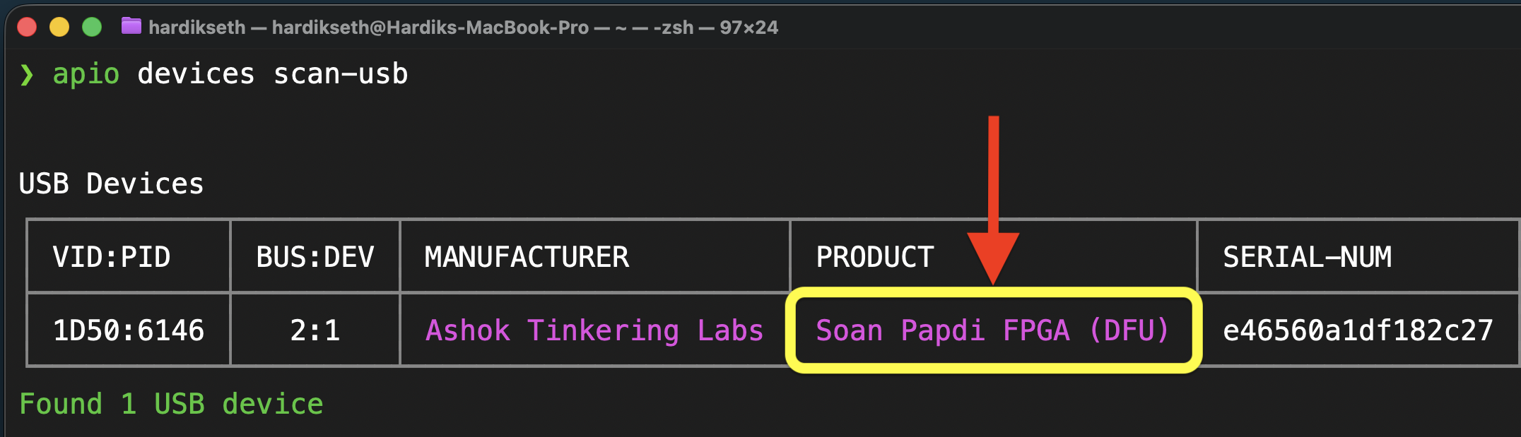
- Synthesize and build the circuit:
apio build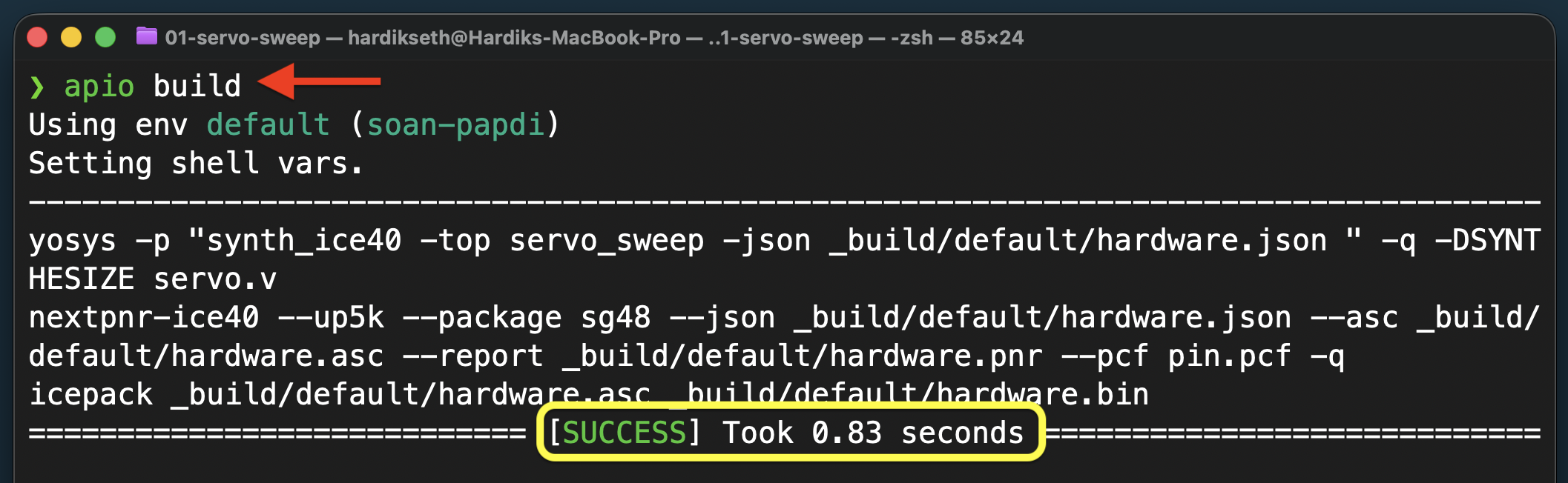
- Upload the final bitstream to the FPGA:
apio upload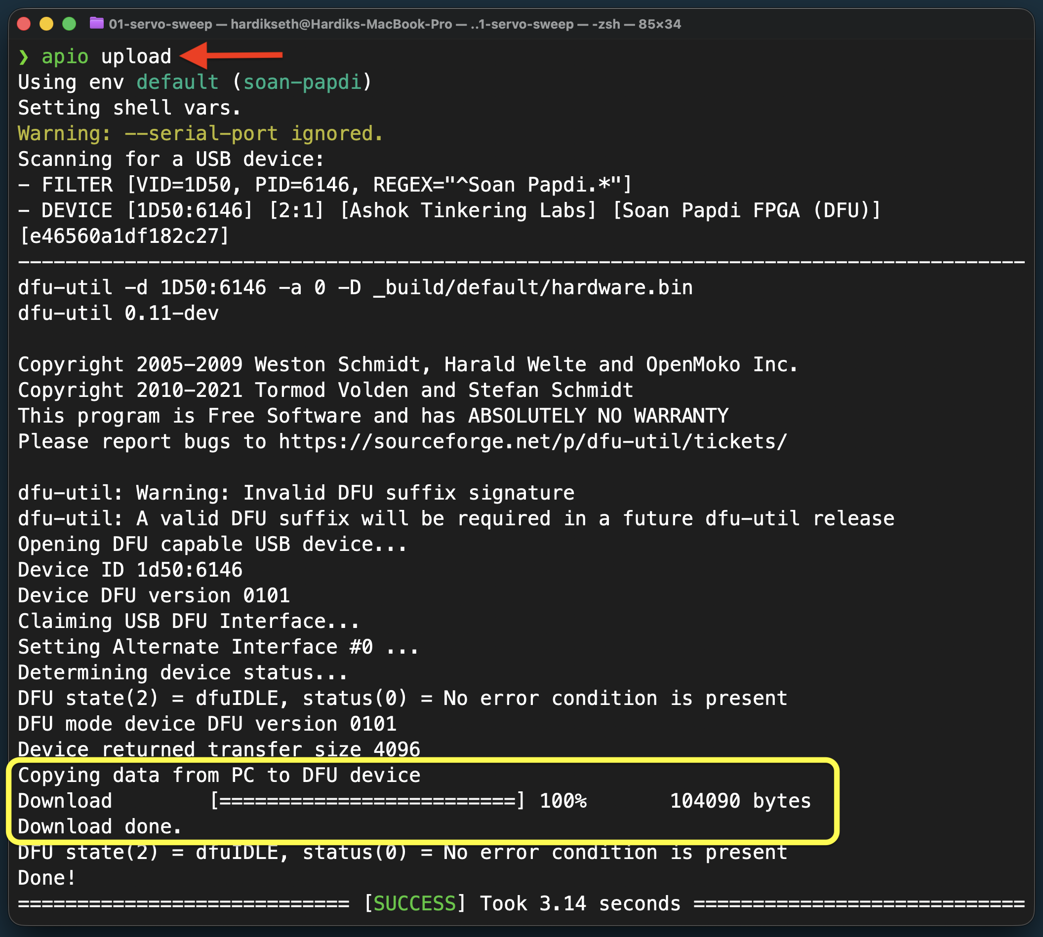
Once the upload is complete, press the reset button on the board. The servo will start sweeping back and forth!
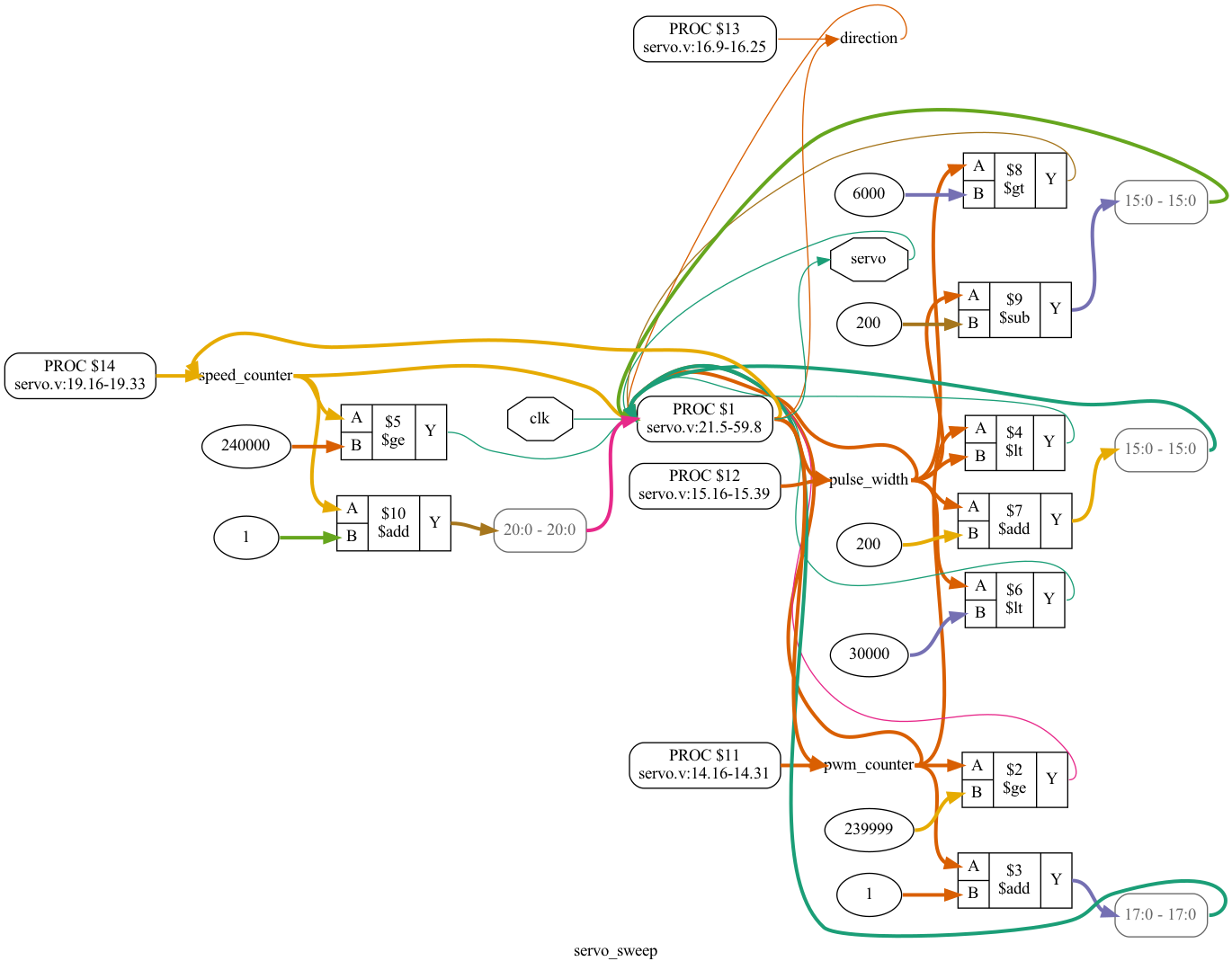
Bonus: Visualize Your Logic
Want to see what your digital circuit actually looks like? Apio can generate a logic graph for you. Run this command:
apio graph --pdfThis creates a visual representation of your Verilog module inside the _build directory. Open the PDF to inspect exactly how your counters, comparators, and registers were physically wired together by the toolchain!