1. Turn on an LED
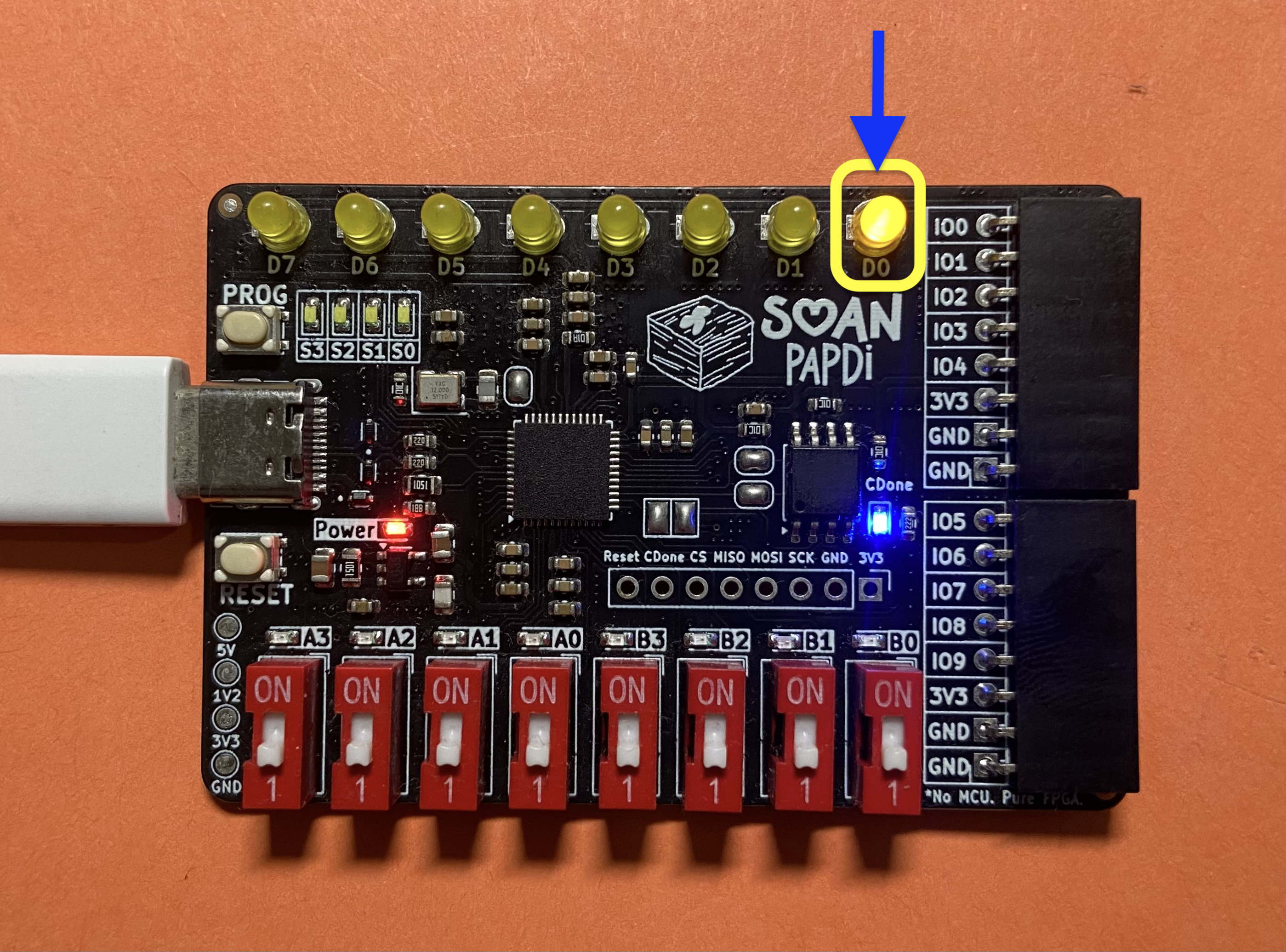
In this project, you’ll turn on an onboard LED on the Soan Papdi board using Icestudio’s visual logic blocks.
What You Will Need
- Soan Papdi FPGA Board ➜ Link
- USB Type-C data cable
How FPGAs Work (The Basics)
Before we start clicking buttons, let’s understand what we are actually doing.
Think of an FPGA (Field Programmable Gate Array) as a giant box of digital Lego blocks. Unlike a normal computer chip that reads instructions line-by-line, an FPGA lets you physically wire up electronic circuits inside the chip.
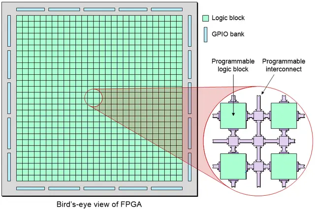
In this project, we are going to create a very simple circuit. We will connect a constant power source directly to the pin where our LED is attached.
Select the Board
First, we need select the Soan Papdi board.
- Look at the bottom-right corner of iCEstudio.
- Click on the Select board dropdown icon.
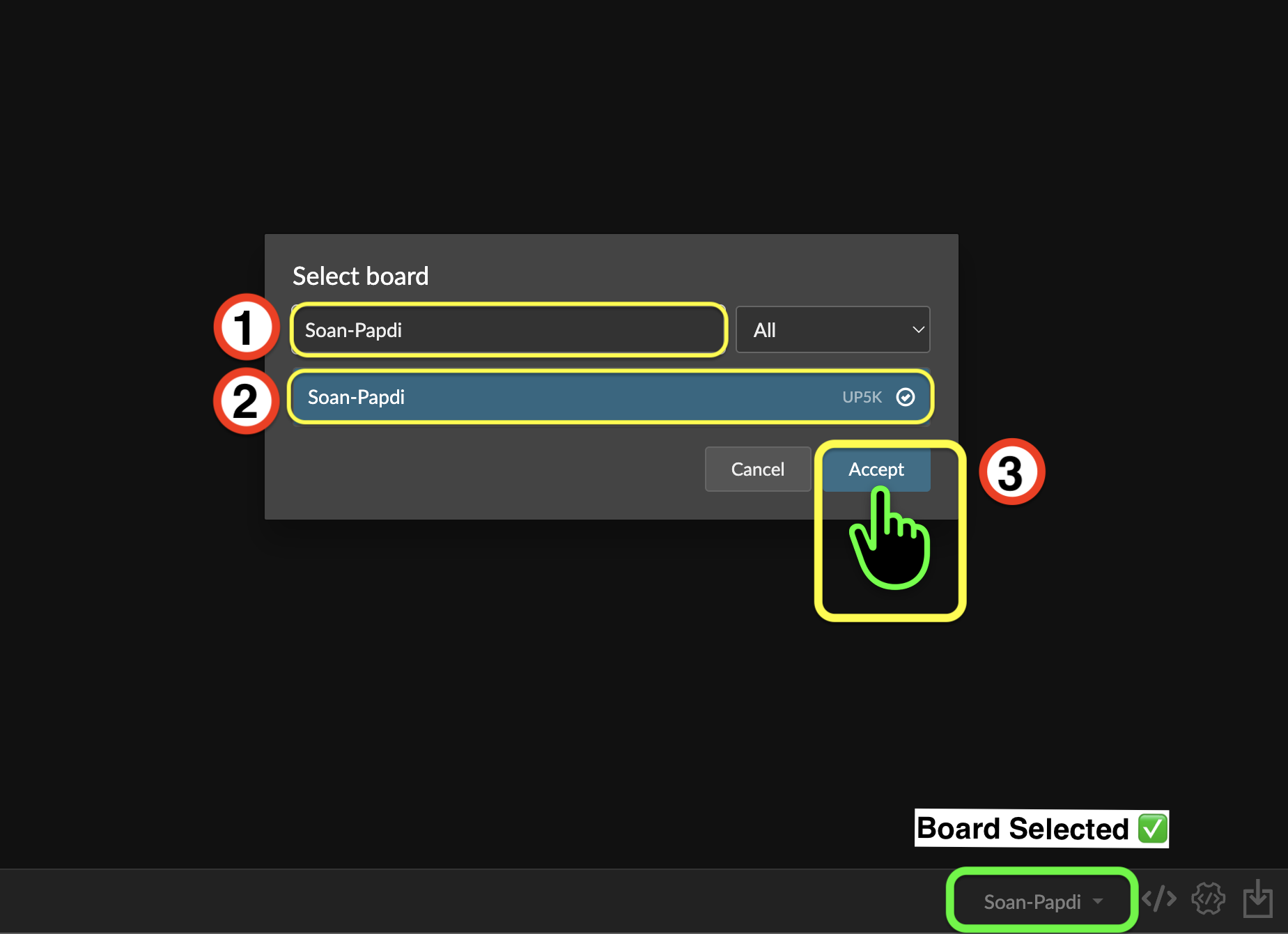
- Choose Soan Papdi from the list.
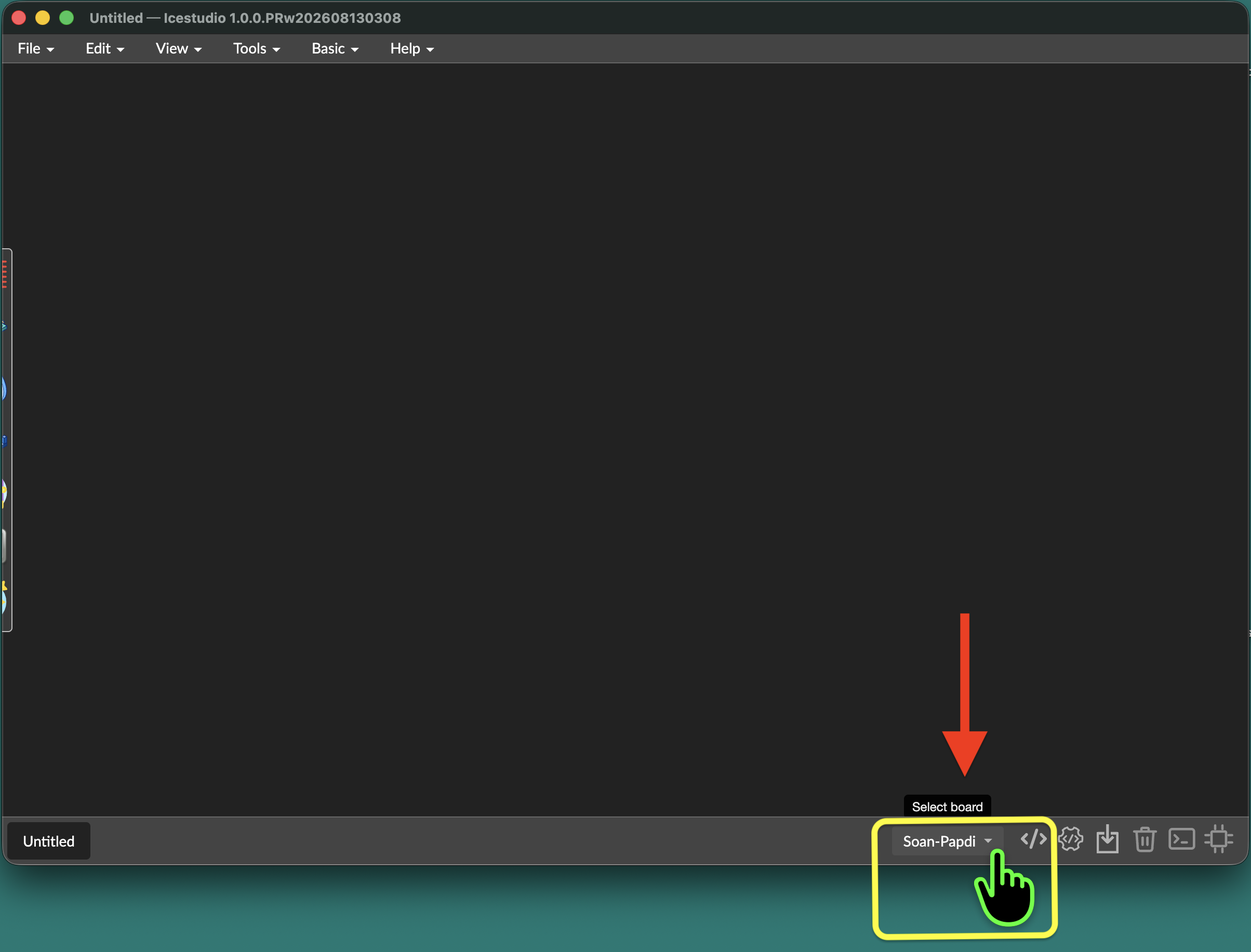
You will see the Soan-Papdi board name confirmed in the bottom-right corner.
Open the “One LED” Example
Let’s open the “One LED” example from the icestudio examples menu.
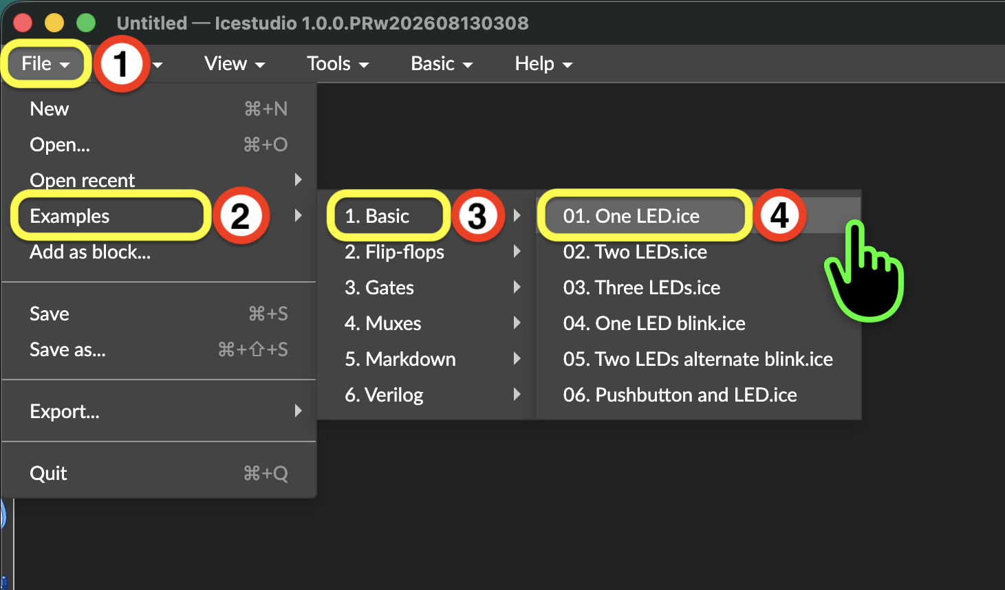
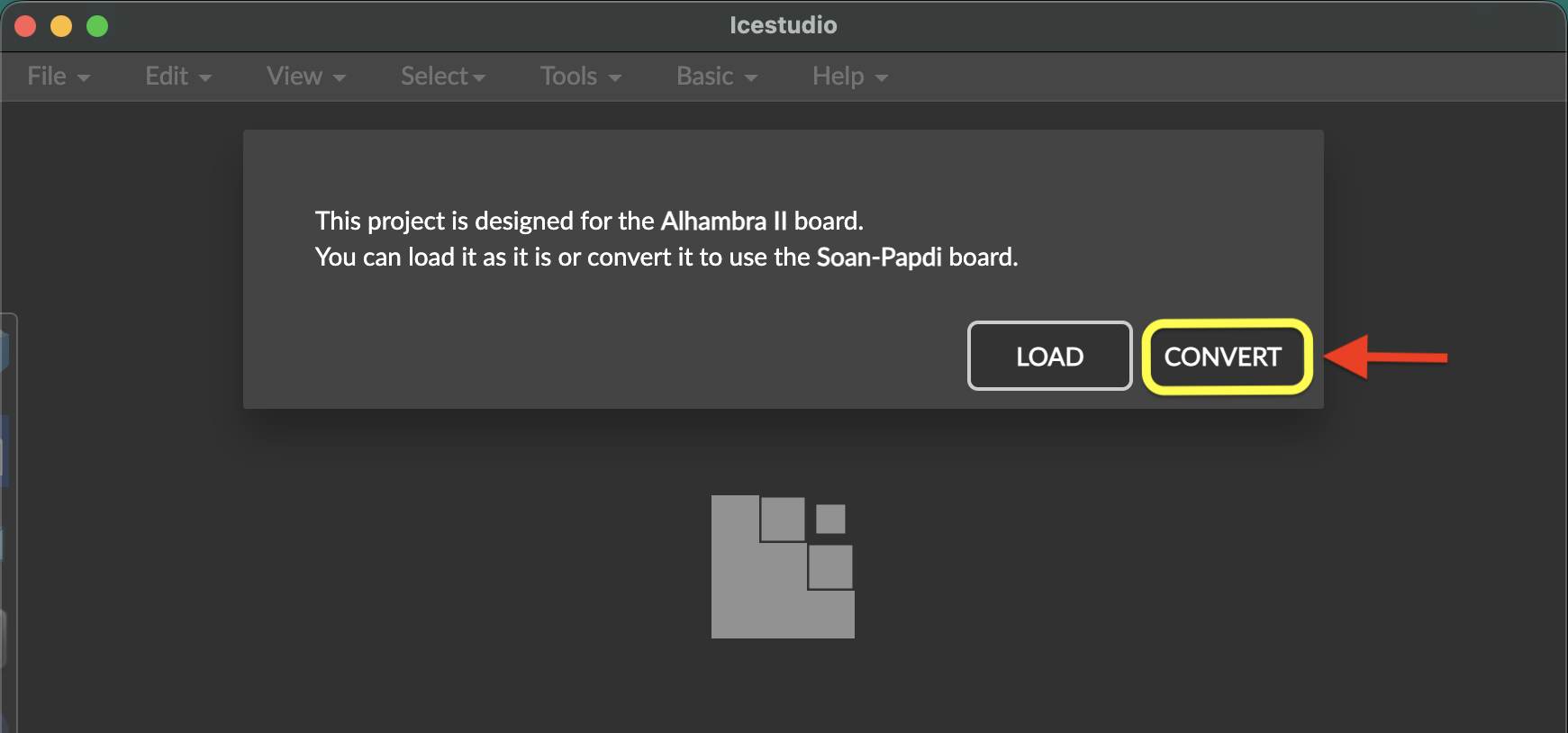
When you open this example, icestudio ask you to convert the pin mappings for Soan Papdi.
- Click on
Convertto continue.
Understand the Blocks
Let’s look at the two blocks on your screen. This is our visual circuit!
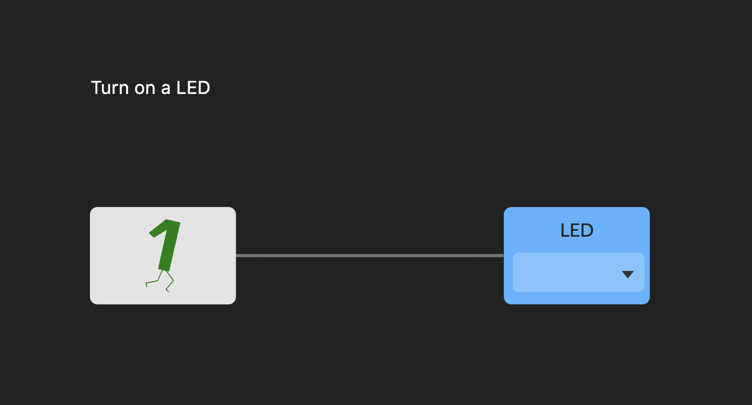
How It Works?
Bit 1: This block provides a constant digital High (1) signal.If you double-click the block, you can see the Verilog code behind it. It simply assigns a constant
1to the output.//-- Constant bit-1 assign q = 1'b1;LED: This is an output block. It takes the signal from theBit 1block and sends it out to a selected physical pin on the FPGA board.
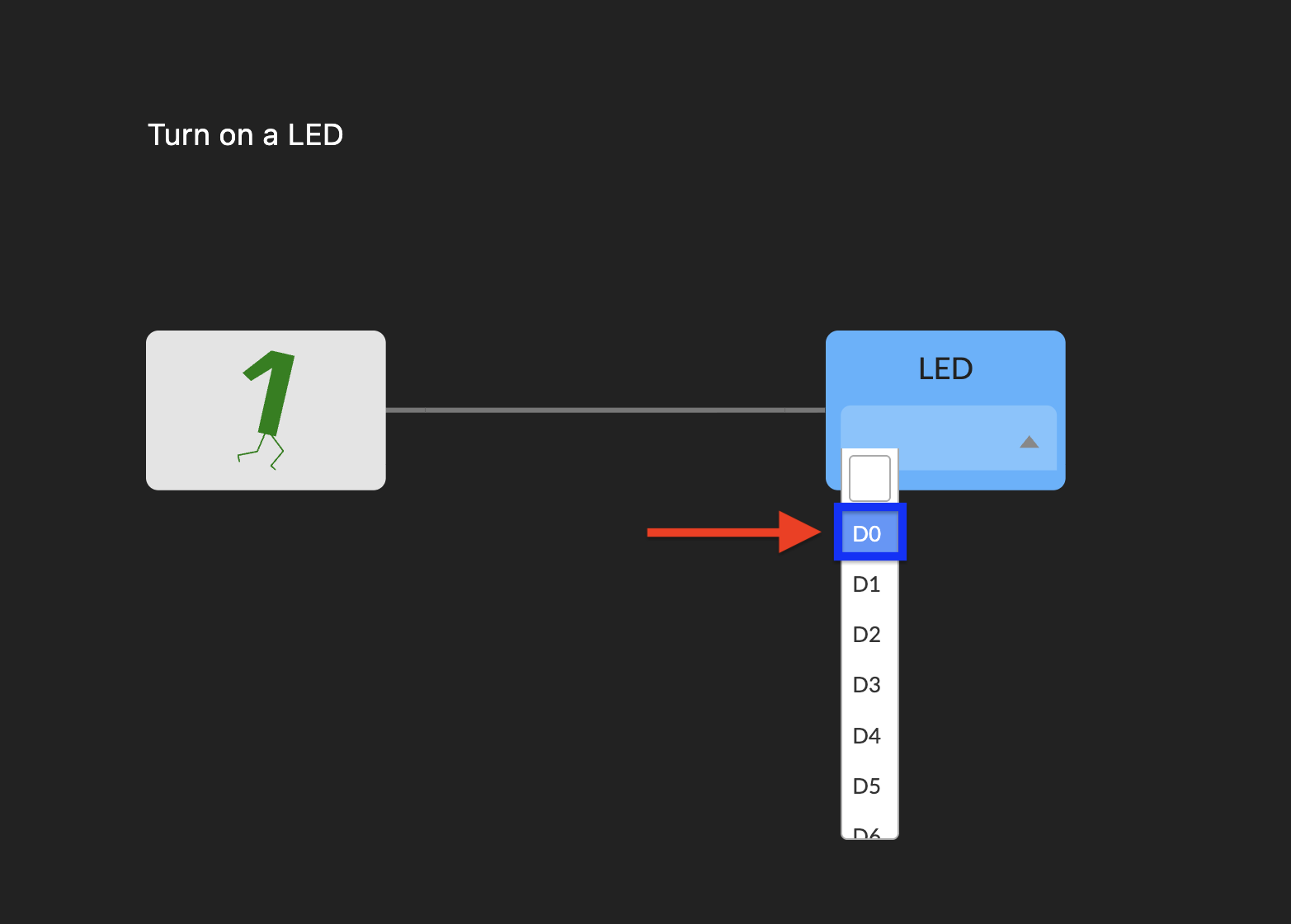
Choose the LED pin:
We need to tell the LED block which physical LED to turn on.
- Click the dropdown on the
LEDblock. - Select D0. (You can choose other output pins later, but let’s stick with D0 for now).
Build Your Project
Our circuit is drawn, we need to “Build” it.
Building translates our visual blocks into a special file (called a bitstream) that the FPGA hardware can actually understand.
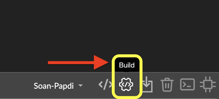
- Click the Build button in the bottom-right corner.
Upload Your Project
Your bitstream is ready. Now, let’s upload it to the Soan Papdi.
Step A: Put the Board in Programming Mode
Before the board can accept new bitstream, we have to wake up its “programming mode.”
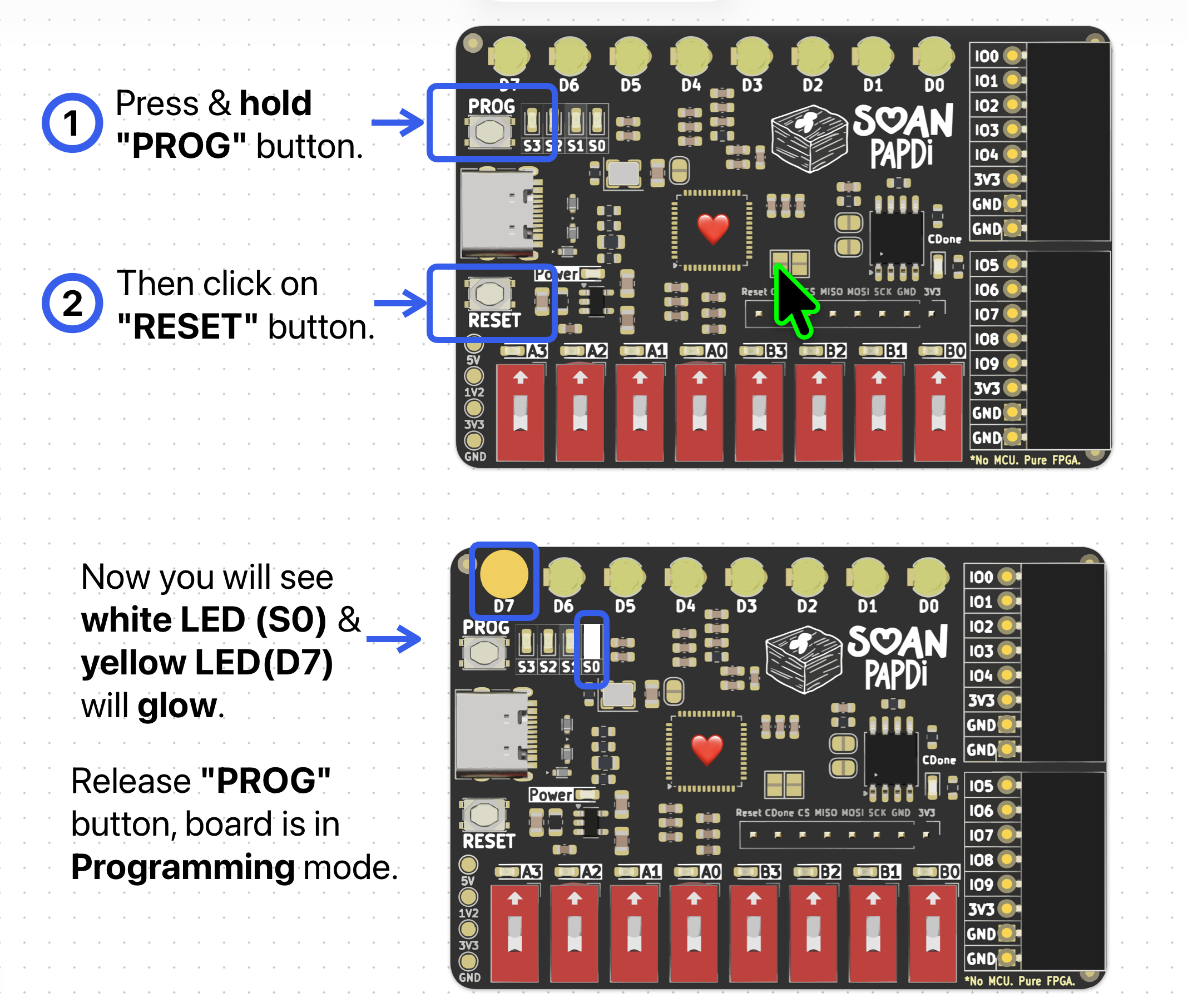
Follow these exact steps on your board:
- Press and hold the PROG button.
- While still holding PROG, press and release the RESET button.
- You will see the S0 white LED and D7 yellow LED glow.
- Now, release the PROG button.
- The S0, S1, and S2 white LEDs will start blinking. This means the board is ready and waiting for your project!
Note
If your project ever fails to upload, always check if you remembered to put the board in programming mode first!
Step B: Upload the Bitstream
Now, let’s send our project to the board.
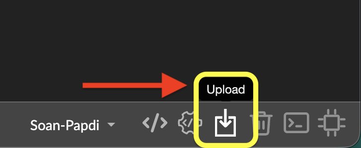
- Click the Upload icon in the bottom-right corner of iCEstudio.
Wait for the upload to complete.
- Once the upload is complete, press the RESET button on the board to start running your new design.
The blinking programming lights will stop, and your D0 LED should now be glowing brightly!
Congratulations! You have successfully programmed your first FPGA circuit.